— Welcome to Enner
— Welcome to Enner

Case1
-
01
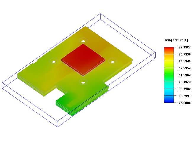
Design Introduction
Maximum temperature of heat source : 77.19℃
Temperature rise: 51.19℃ -
02
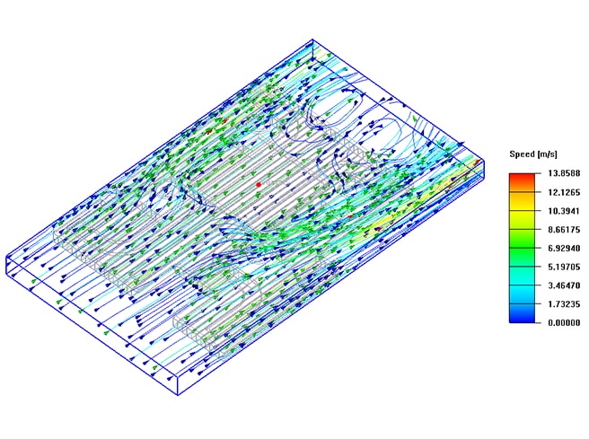
Design Introduction
Vmax 13.85(m/s)
-
03
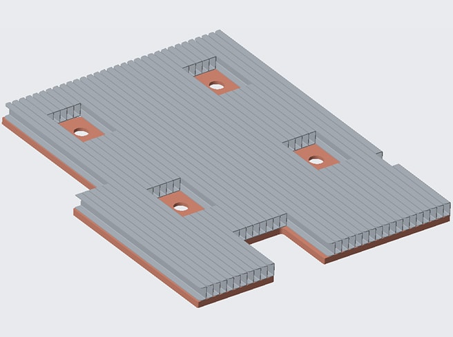
Design Introduction
In this scheme, heat pipes are used for heat dissipation, and fins are added to the condensing section of heat pipes to expand the heat dissipation area, so that the chip with high heat flux can be effectively cooled by conventional forced air convection cooling.
After the actual test of the sample, it is confirmed that the stable temperature of 77℃ within 0.3 minutes by using the heat pipe cooling scheme can not meet the heat dissipation demand. -
04

Heatsink performance test report
-
01
-
02
-
03
-
04

Case2
-
01
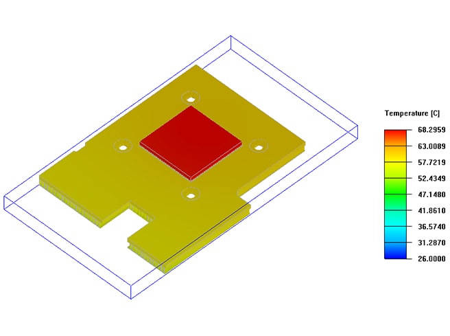
Design Introduction
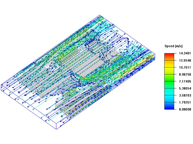
Maximum temperature of heat source : 68.29℃
Temperature rise: 42.29℃ -
02
Design Introduction
Vmax 14.38(m/s)
-
03
Design Introduction
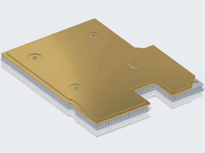
This solution uses a VC vapor chamber for heat dissipation, which can make direct contact between the heat source and the equipment, thereby reducing the thermal resistance, better allowing heat to be taken away from all directions, and making the surface temperature of the product more uniform.
After actual inspection and testing of samples, it was confirmed that using the VC heat dissipation solution, the stable temperature is 69°C within 0.3 minutes, meeting the customer's heat dissipation needs. -
04
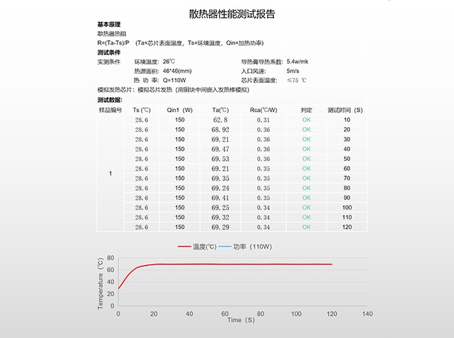
Heatsink performance test report
— Welcome to Enner
Analysis of Test Results
According to above test results, given the same heat dissipation demand, different structural designs lead to different performances.
Case 1 Heat Pipe Design: can not meet customer's heat dissipation demand.
Case 2 Vapor Chamber Soaking Plate Design: can meet customer's heat dissipation demand.
Data Analysis of Heat Pipe Design Test and Vapor Chamber Design Test
- Case1 (Heat Pipe)
- Case2 (Vapor Chamber)

This project has been designed and developed based on ENNER analysis report case1 and is currently in mass production


 Crystal Xi


 Leave message